OKPW / Case study
London SW12
Dornton Road
Main contractor
London SW12
Two chimney breasts carried on new steel, so a ground-floor flat could open out to the garden
Two existing chimney breasts had to be carried on new steel before the ground floor below them could be opened out to the garden, in a ground-floor flat with people living in the flats above throughout. OKPW was the main contractor: the strip-out, the steel, foundations cast in pins, a wrap-around rear and side-return extension, a new floor through the whole flat, and the fit-out. The structural drawings are explicit about what they assumed was behind the walls, and ask for each assumption to be checked once the work was open.
- Dwelling
- Ground-floor flat
- Floor area
- 115m² GIA
- Extension
- 3.0m deep
- Foundations
- From 1.0m, in pins
- Completed
- 2025
The job
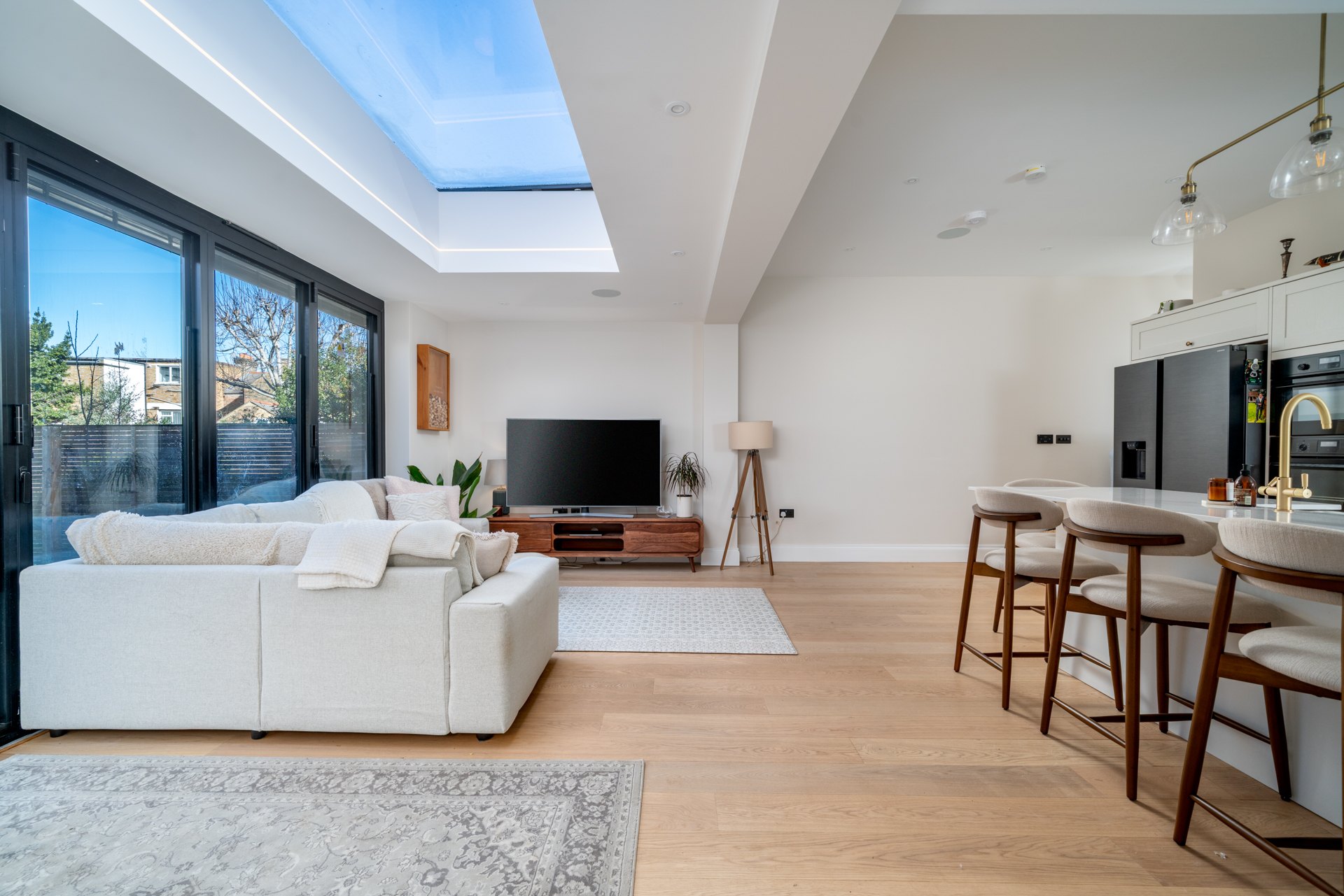
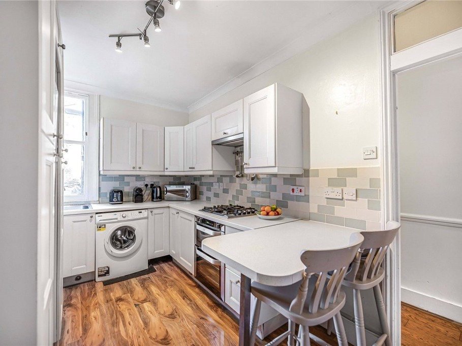
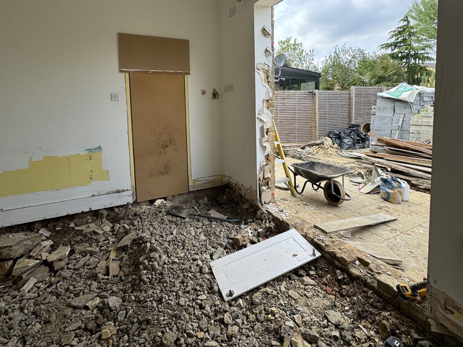
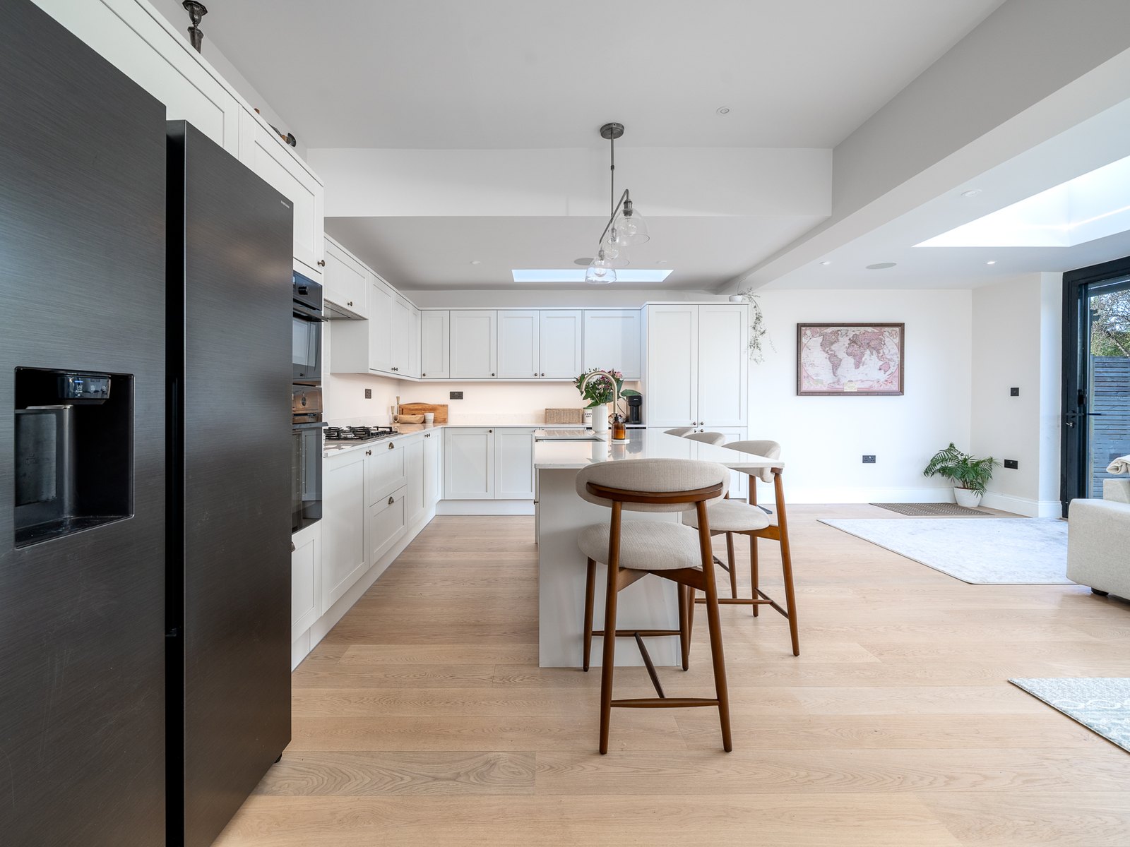
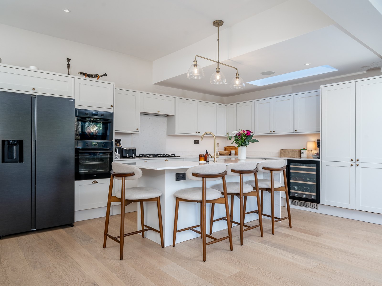
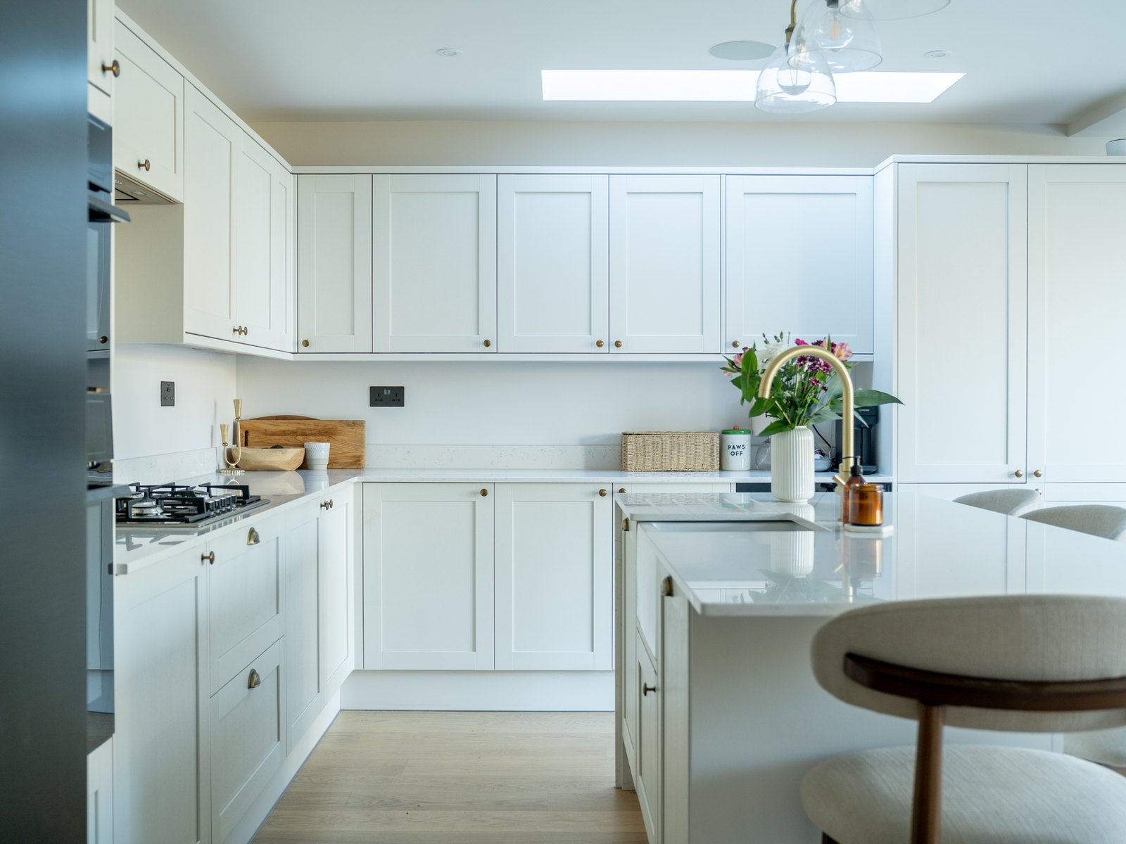
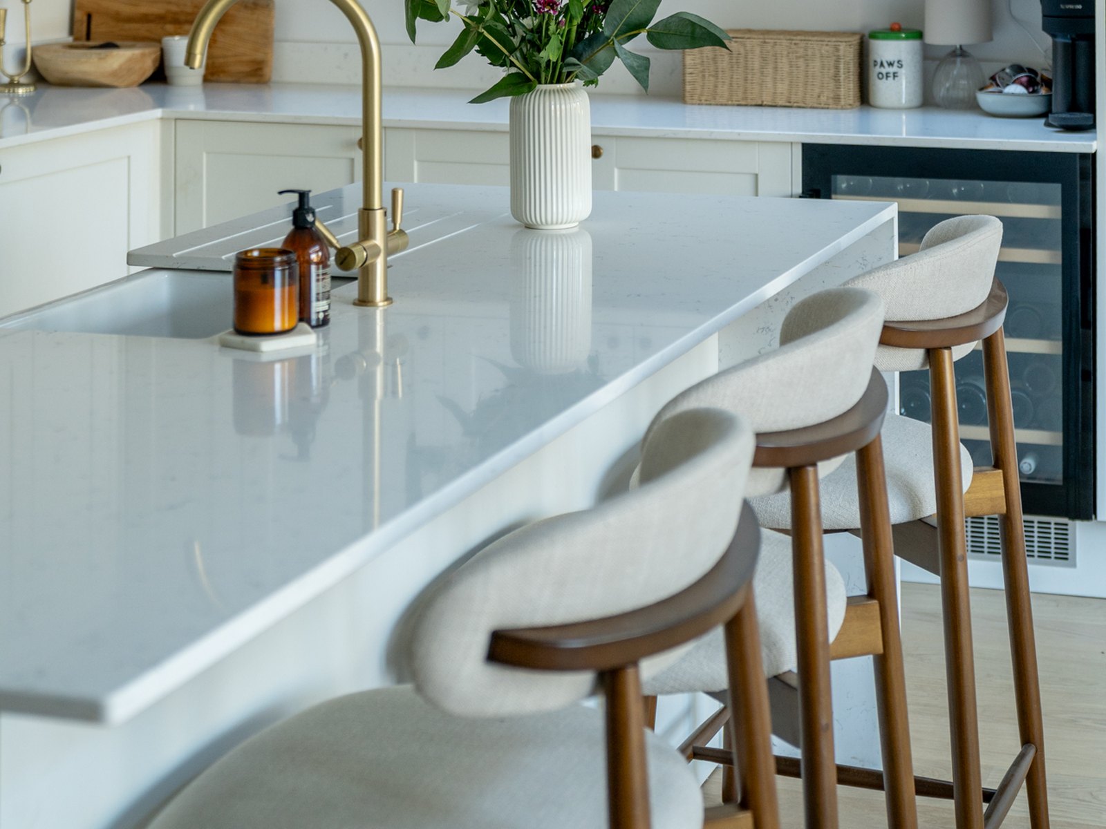
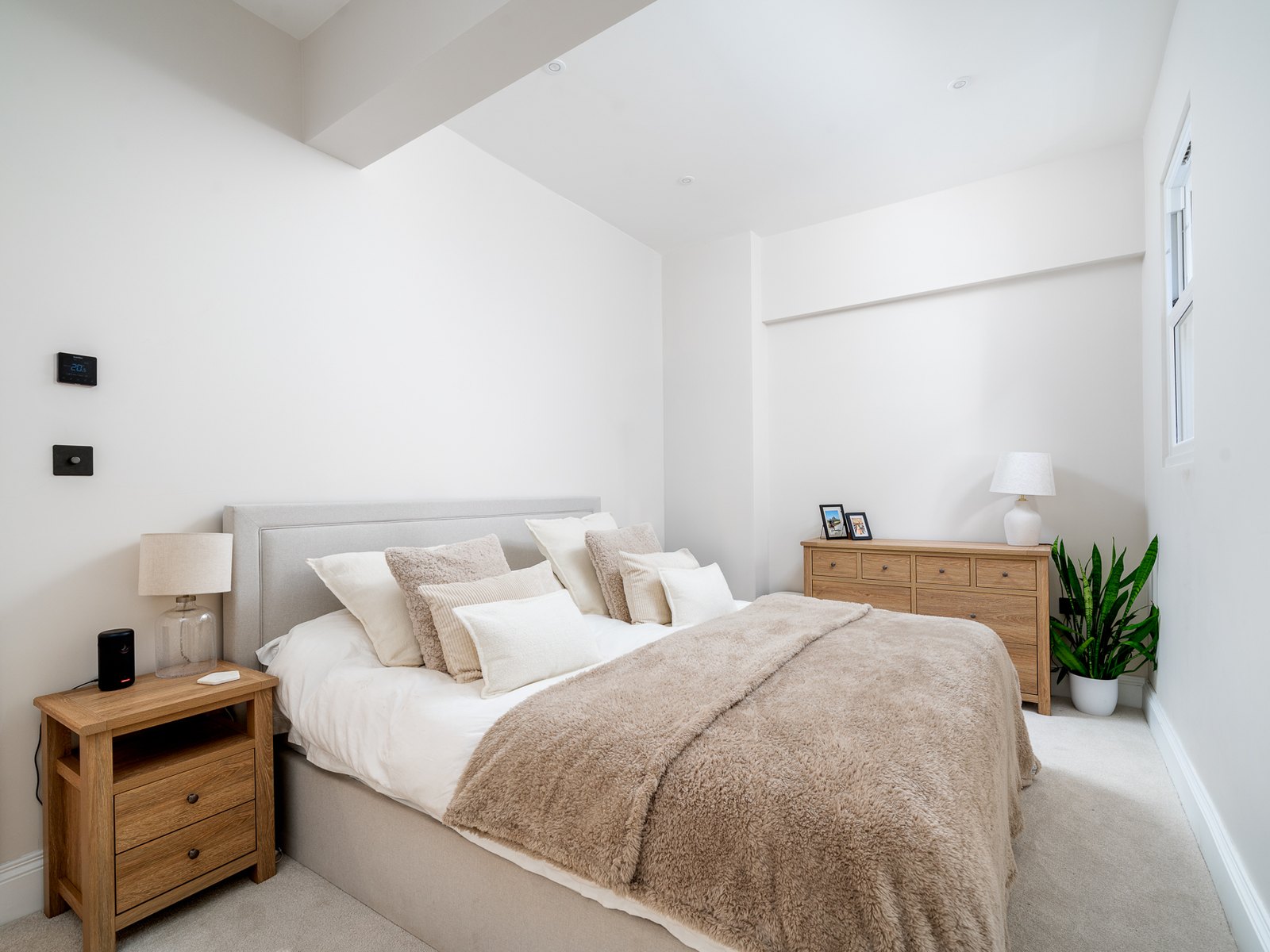
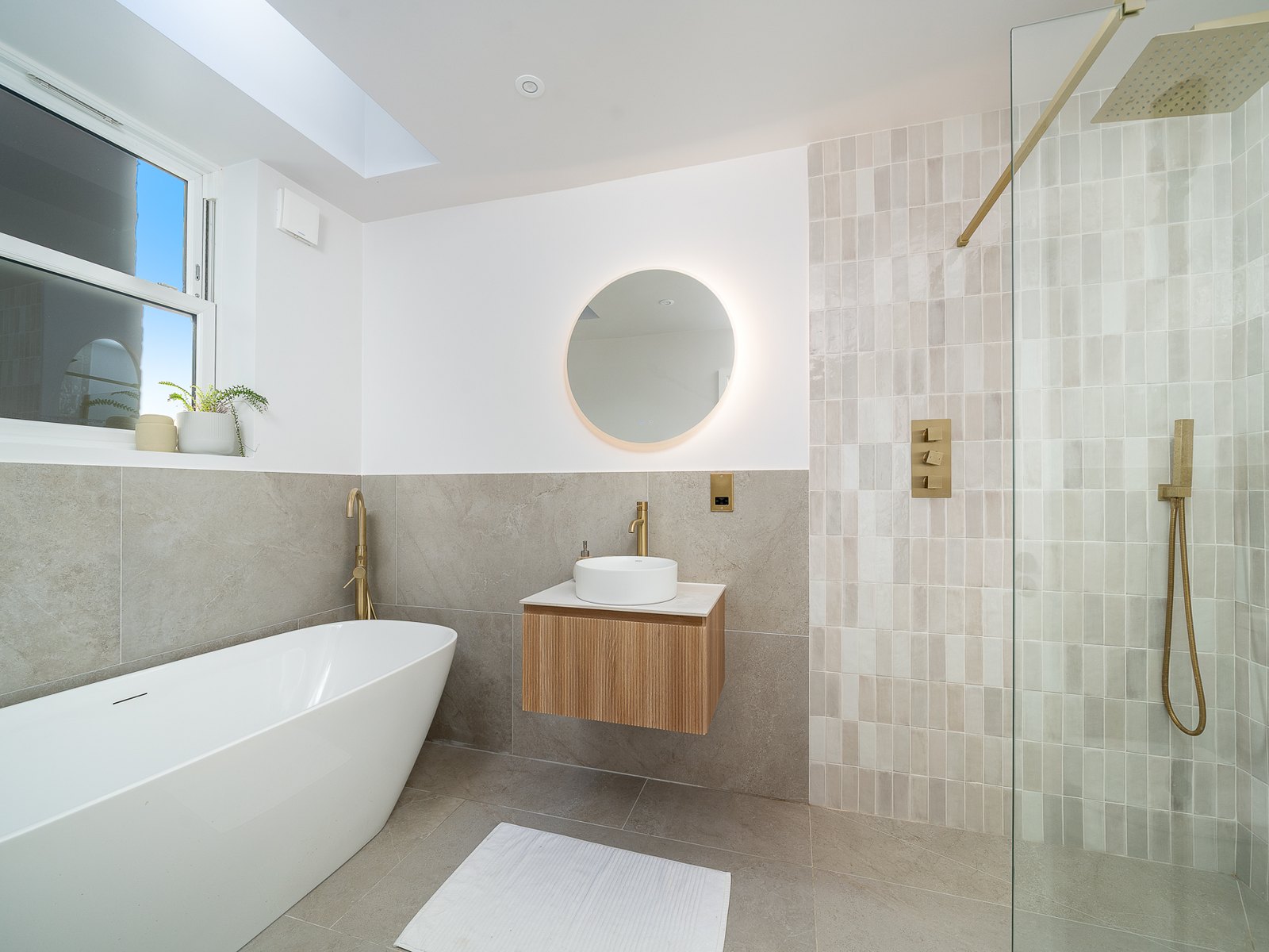
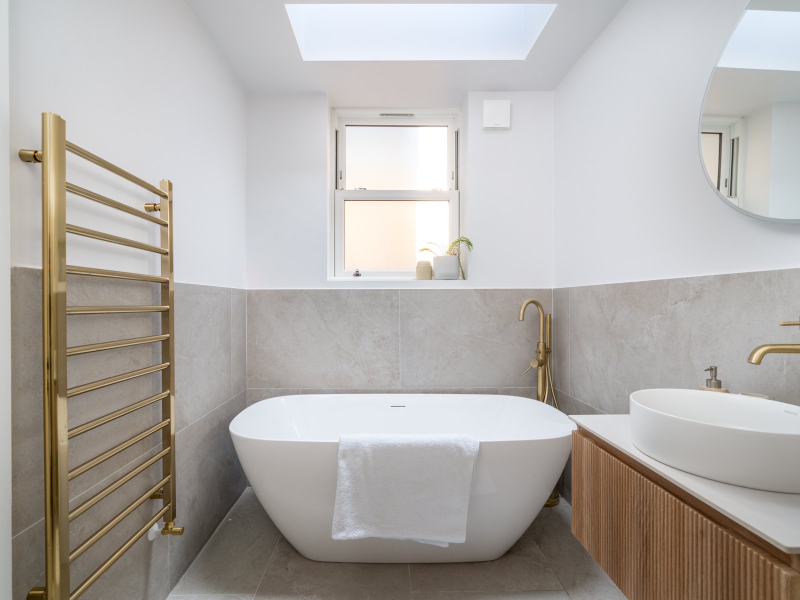
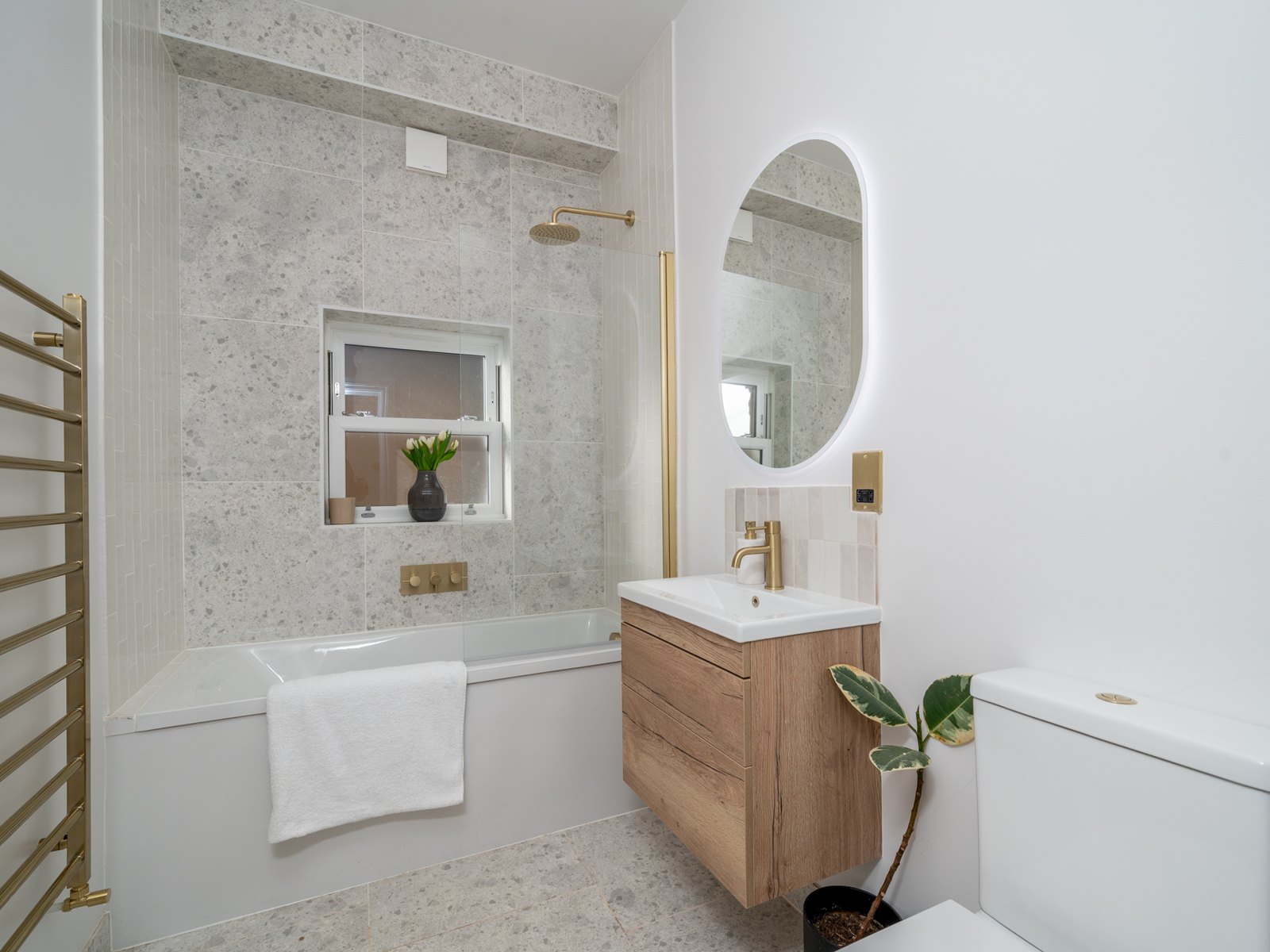
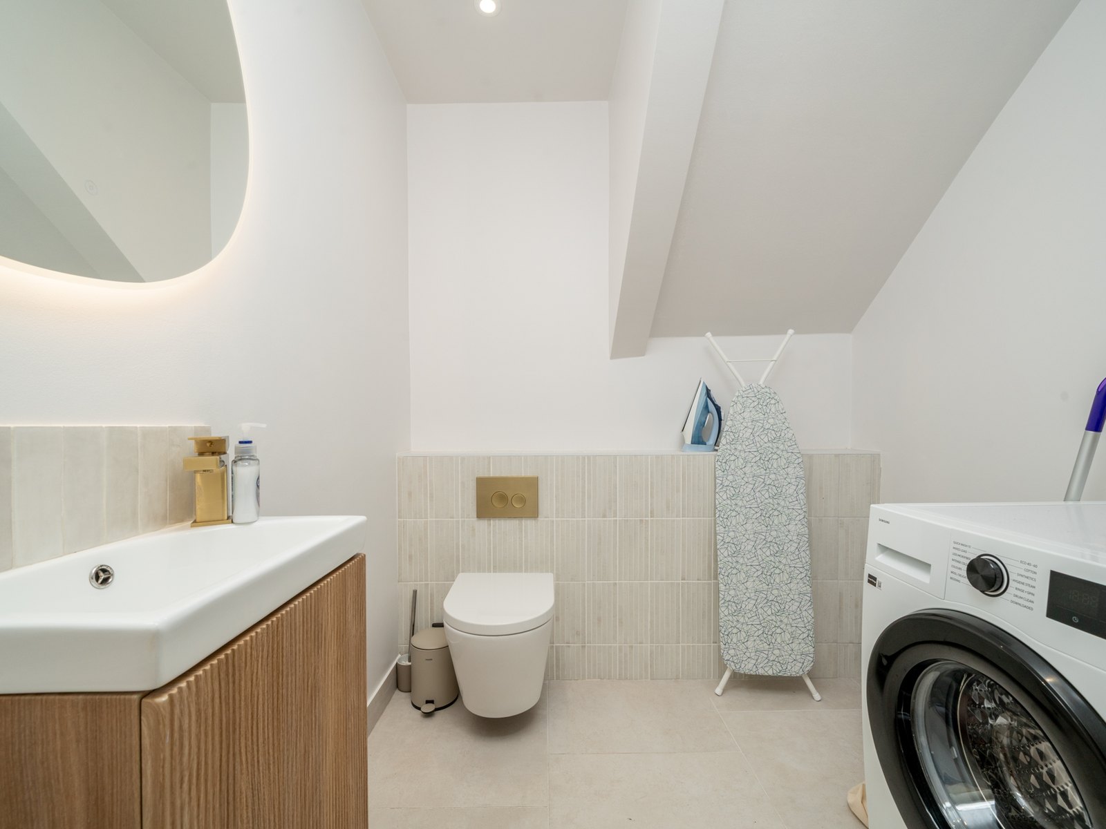
Our client owned the ground-floor flat; the flats above stayed occupied for the whole job. The brief was a wrap-around extension, rear and side return together, to a flat of 115m² GIA, with the layout reworked behind it: an open kitchen, living and dining space on the garden with an island kitchen, three bedrooms, a bathroom, an en-suite and a utility room with a WC. We did everything except fit the folding doors and the rooflights: strip-out, structure, foundations, drainage, walls, floors, roof, carpentry, electrics, plumbing, heating, the kitchen and every finish.
Carrying the chimney breasts
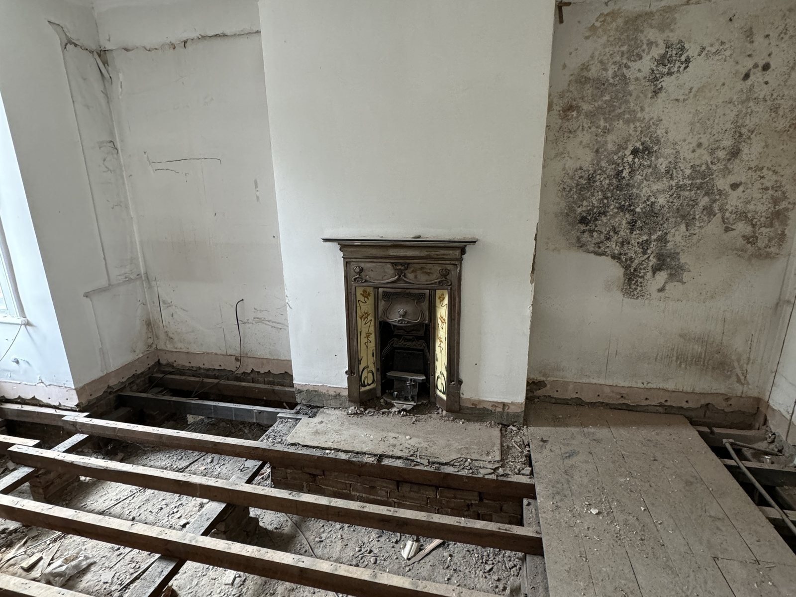
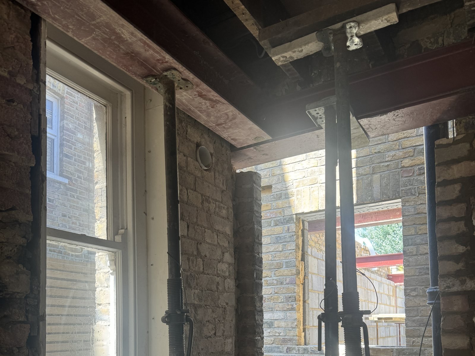
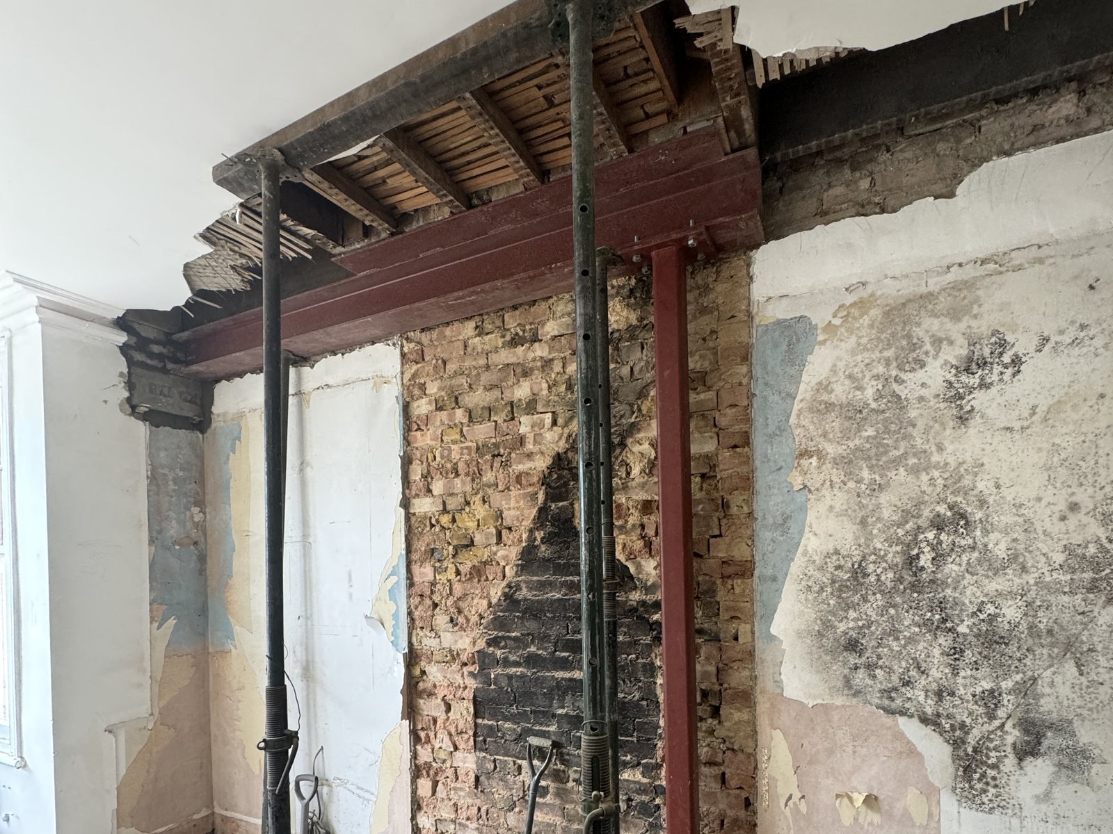
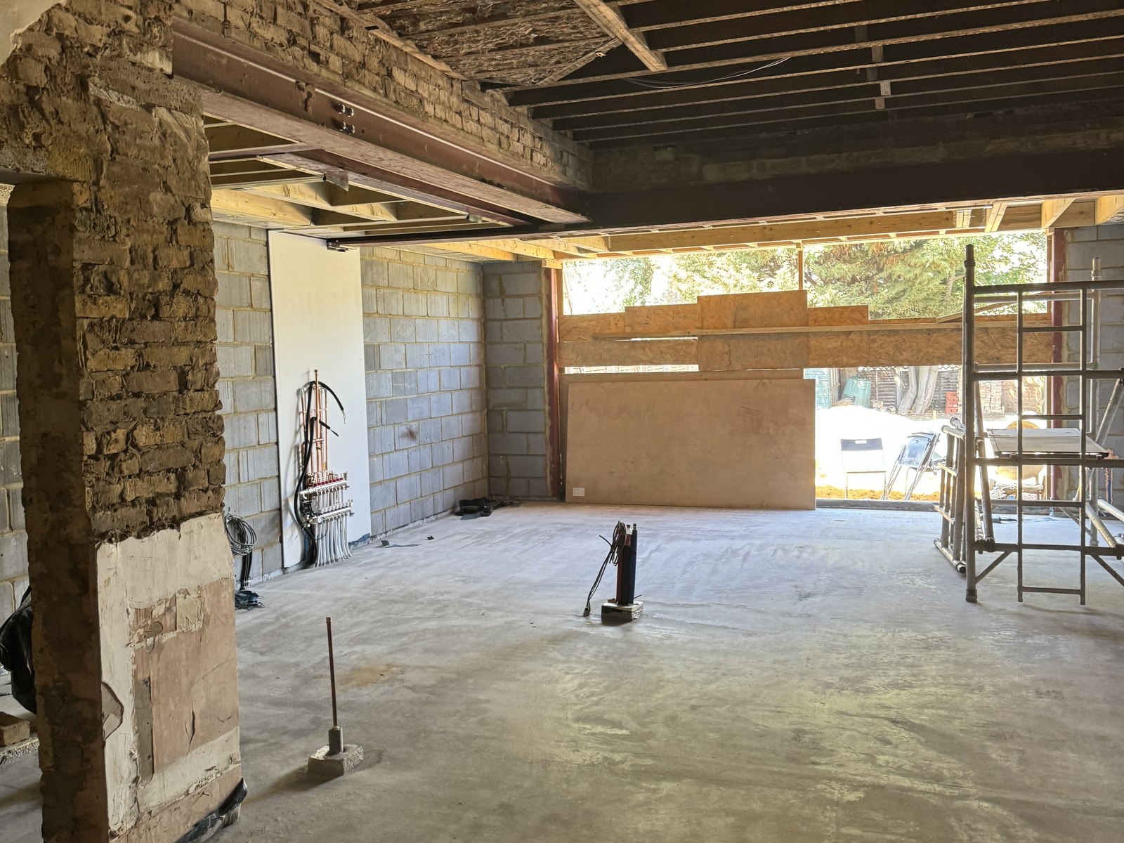
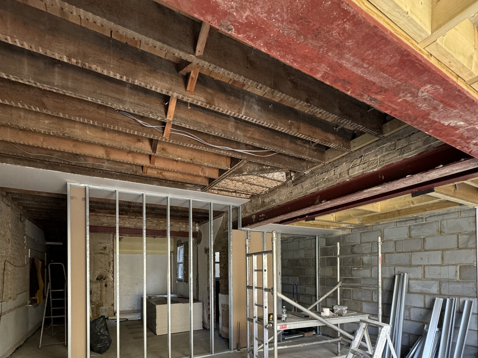
The engineer’s drawings put two existing chimney breasts above the opening and took them onto new steel. BF1 and BF2 are each a 203 × 203 × 46 UC, with a 10mm steel plate welded to the top flange to match the length and width of the breast it carries. BF1 bears on a padstone at one end and on C6, a 90 × 90 × 8 SHS column, at the other. BF2 sits on C1, a 100 × 100 × 10 SHS column, and ends on a lintel at the far side. In the front room the chimney breast was taken out and a steel beam put in to carry what is above it. Each column stands on a 15mm base plate bolted into its own pad foundation. Our programme specified that every beam be cased for an hour’s fire resistance, painted with a coat of zinc-rich primer, and checked and approved by the building control officer.
What the drawings had to assume
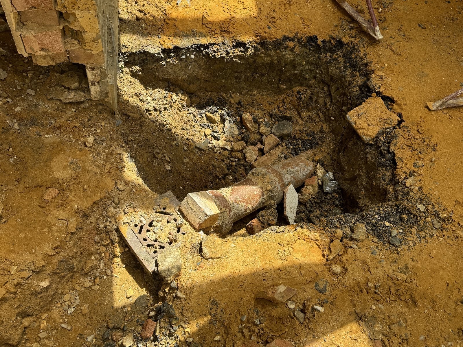
Several notes on the structural drawings say what was assumed rather than known. The foundation under the existing wall was to be exposed and confirmed before any new beam went on top of it. Existing supports hidden in the ceiling were to be exposed before the main wall came down, with the arrangement agreed with the engineer. The pad that underpins the spine wall’s existing foundation was drawn subject to site findings, to be detailed once it was exposed and inspected. The floor in the extension was taken lower than the old one, and every pad is drawn with its formation at least a metre below existing ground, subject to site findings and confirmation with the local building control officer. The ceiling plan went through seven issues, P1 to P7.
Foundations in pins
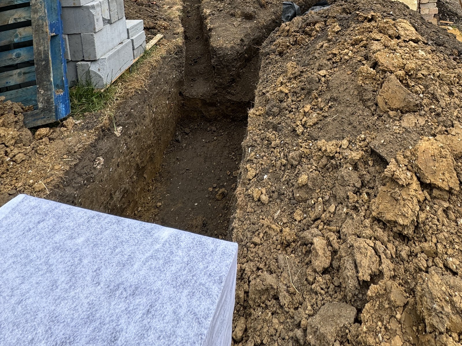
The new walls stand on a strip foundation 600mm wide and at least 500mm deep, in C35 concrete, cast in pins no longer than a metre. The pins are numbered in a hit-and-miss order: the next number is started twenty-four hours after the last, each pin is concreted on the day it is dug, and no two neighbouring pins are open together. Each base is inspected by the engineer or the building inspector, and three top and three bottom H12 bars, at least 800mm long, run between the pins. The pads under the columns and under the spine wall are 800mm square and 400mm deep, 600mm on one side under C6.
One floor, wall to wall
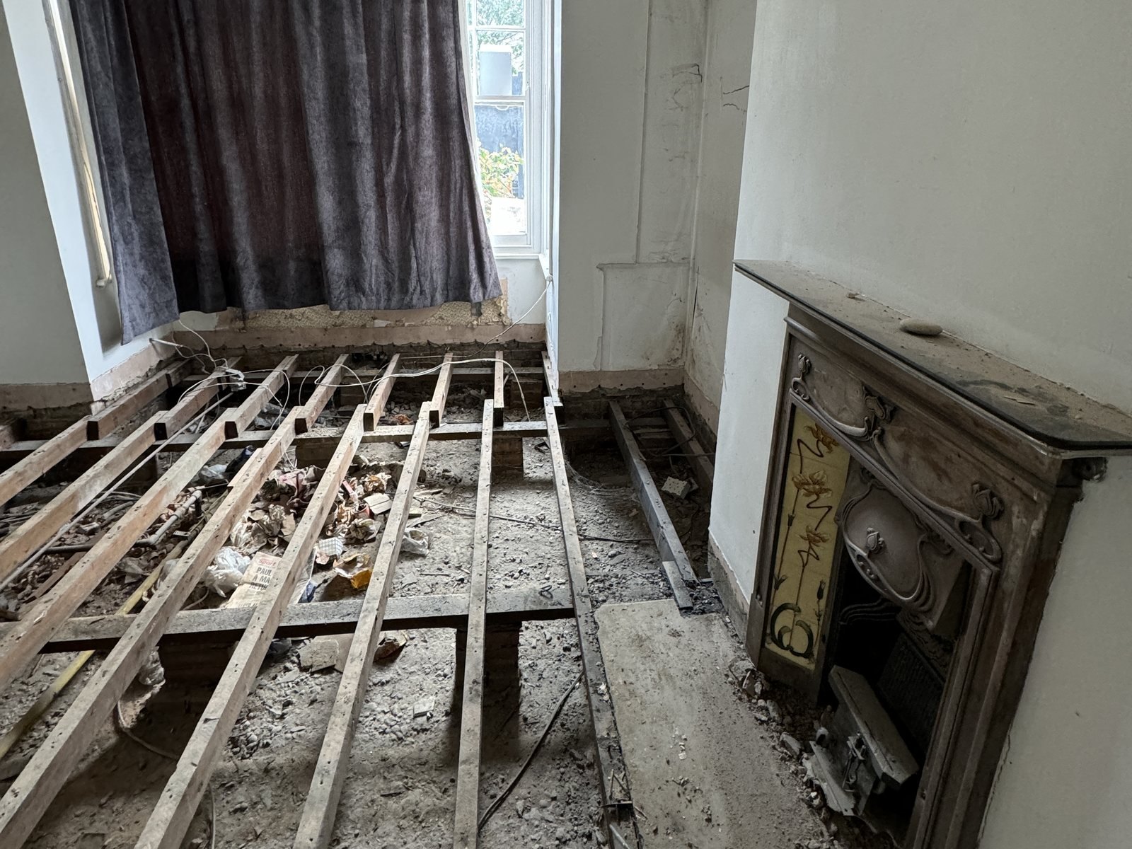
The front room had a suspended timber floor on joists. We took the joists out and laid one floor through the whole flat, old rooms and new alike: a concrete slab, a 1200-gauge damp-proof membrane, 100mm of insulation, then underfloor heating in 70mm of CemFloor across the full area. CemFloor is a liquid screed that warms up and cools down quickly, which makes the heating easy to control. The heating is split into six zones.
Walls and roof
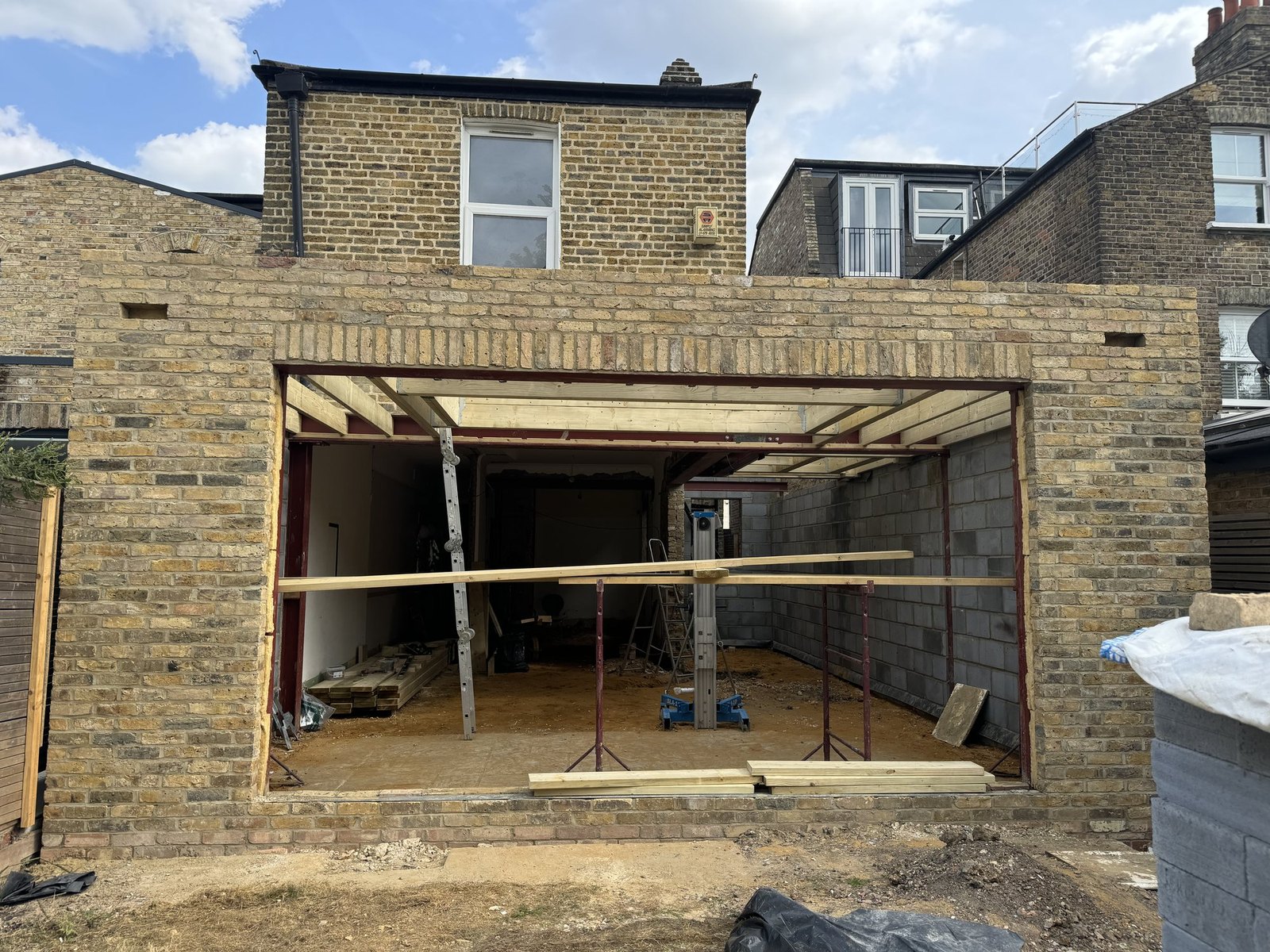
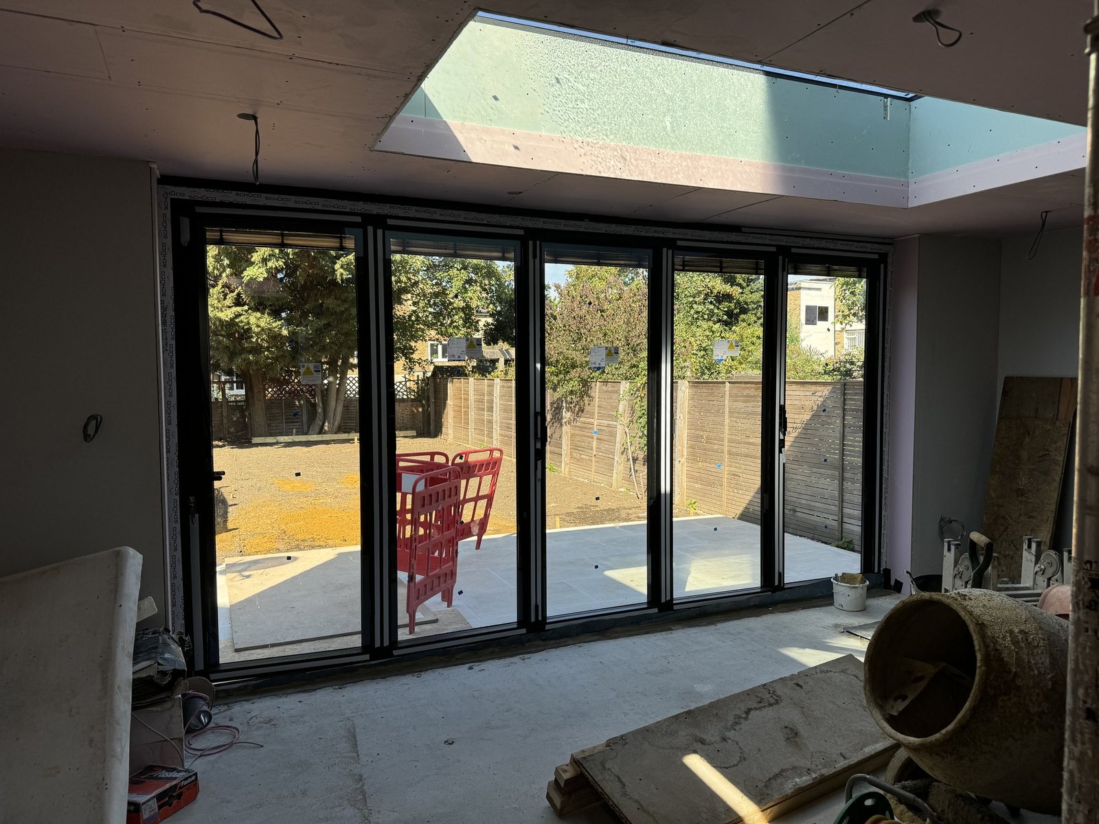
The new walls are a cavity: a 100mm skin of yellow London brick, a 75mm cavity filled with rock wool batts, and a 100mm Thermalite Shield block inner leaf with a plastered finish, tied with stainless-steel ties and linked to the existing damp course. The roof is flat, finished in fibreglass over 100mm Kingspan, with three rooflights trimmed into the joists, and the back wall opens 4,788mm across on a folding door set of five leaves. The doors and rooflights were supplied and fitted by a specialist installer the client chose, who issues the certificates for them.
Heating and services
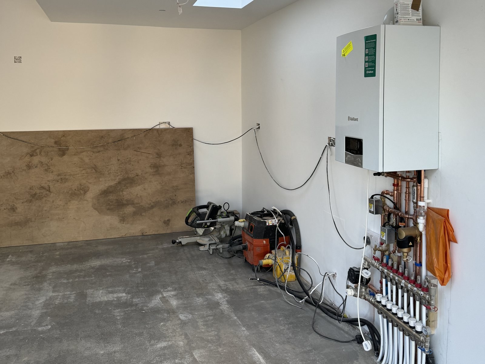
We fitted the boiler, a combination unit in a kitchen cupboard in the extension, and the underfloor heating it feeds. The consumer panel is new, with a fire alarm system and a heat detector in the kitchen, extractors in the bathroom, the en-suite and the utility room, and external lighting at the back and at the front where it is needed. We provide the electrical test certificate on completion and are responsible for testing and certifying the heating.
Quiet for the flat upstairs
The neighbour in the flat directly above could hear every movement below. With the client we agreed a variation to the work: a sound-insulated ceiling, with Rockwool Sound slab laid between the joists before the new ceiling went up.
Every room set out before first fix
Every room was set out on its own sheet before first fix. The electrics set runs to twenty-seven sheets, from the fittings schedule through lighting and then sockets, TV and data for each room. The plumbing set runs to twenty-two: hot, cold and waste points, the extractor holes, and tile layouts that give the direction each tile runs. The bathroom, the en-suite and the WC each have a fixtures schedule behind them.
The garden
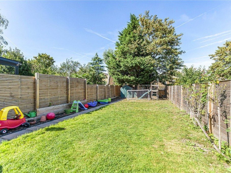
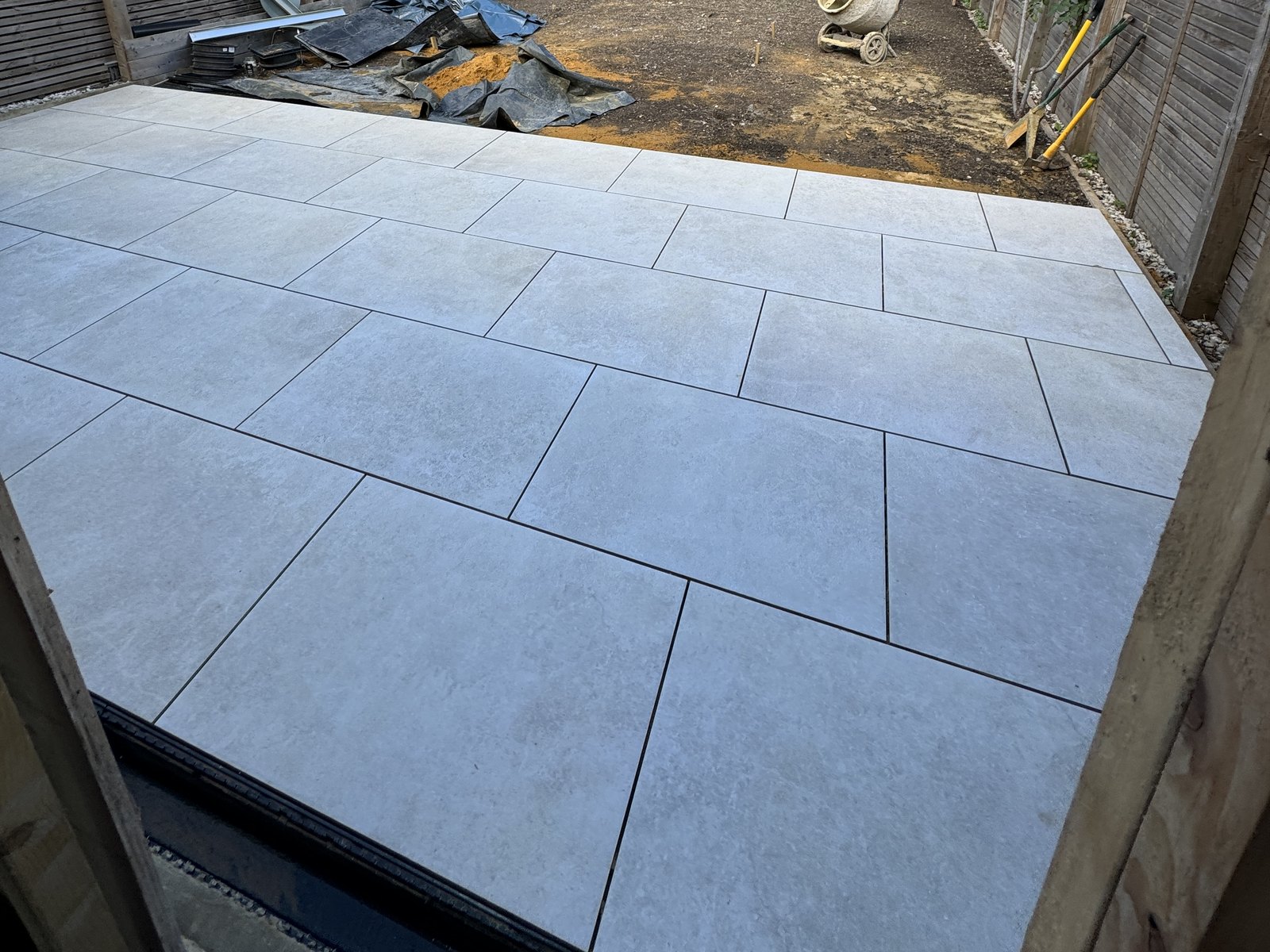
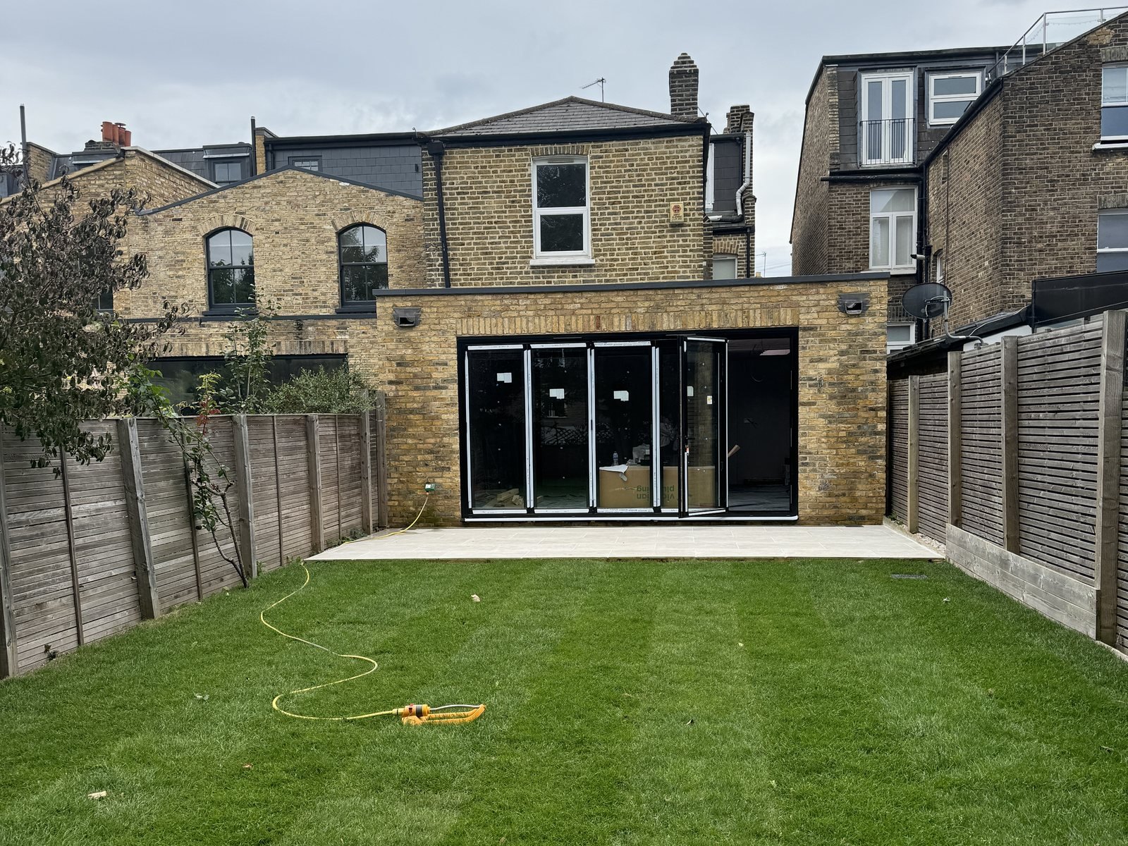
Outside, we cleared the garden completely, levelled it, brought in new soil and compacted it, and laid new turf. The paving at the back of the extension is new.
The programme
The programme ran to eleven stages in a five-month window, with drainage and plumbing in three phases, carpentry and electrics in two, and a week of buffer before completion. Structural demolition was programmed to start only once all the relevant checks and consents had been achieved, and the steelwork was a week of its own. The sheet carries its own caveat, that timelines are estimates and may be subject to change, and the last plate shows it as the plan, not as the sequence that was built.
What this case study does not answer
This is the contractor’s account of the job, so there are things it doesn’t cover. If you’re weighing us up for a tender list, the ones worth asking about are the form of contract and how the final account landed against it, who held principal contractor and principal designer, the building control route and the party wall matters, and who designed the temporary works. The structural drawings pass temporary works to the contractor, and we’ll answer all of them.
The drawings
6 plates
Plate 01
Model

The back of the house as built, as an OKPW model. White is the building that was already there; mint is what we built: the rear extension and the side-return infill with its three rooflights, the folding doors, and the bathroom’s old door bricked up to a new window.
Plate 02
Plan
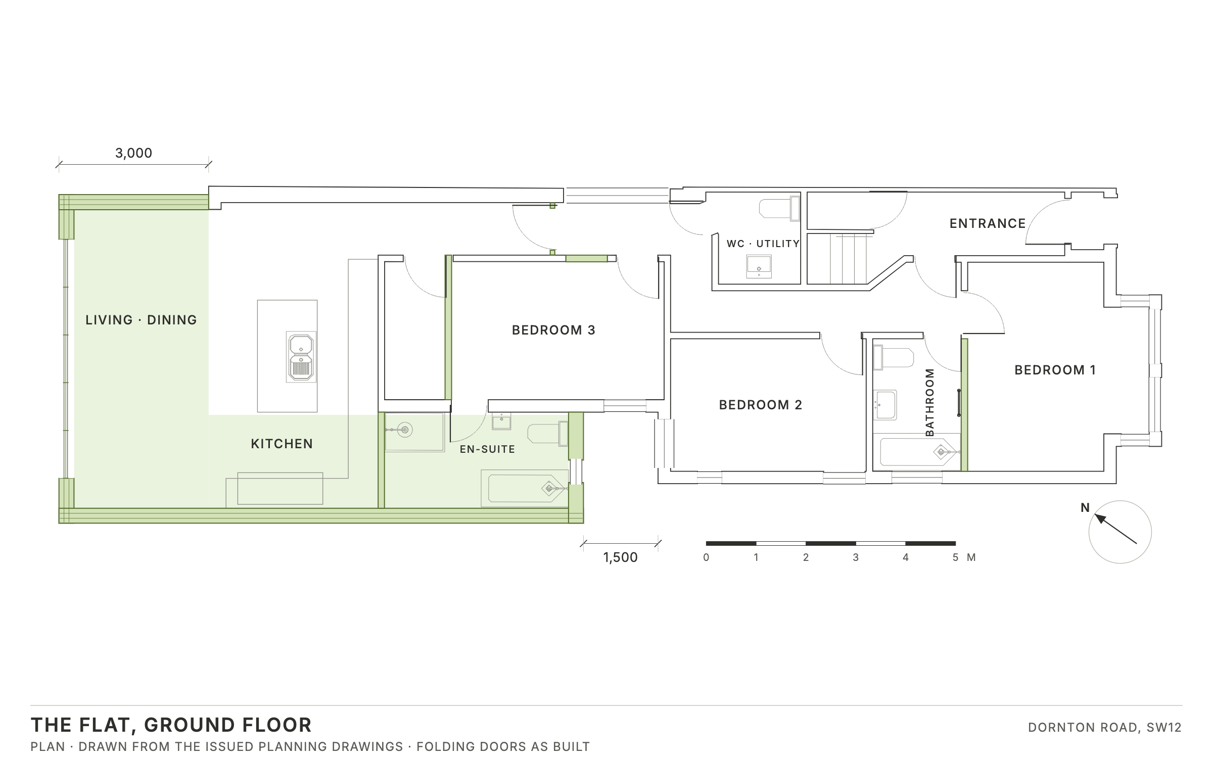
The whole flat at ground floor, drawn to scale from the architect’s planning drawing. The extension and the side-return infill are in the tint; the infill stops 1,500mm short of the house corner, and the back wall opens 4,788mm across. The folding doors are shown as built, with five leaves.
Plate 03
Elevation
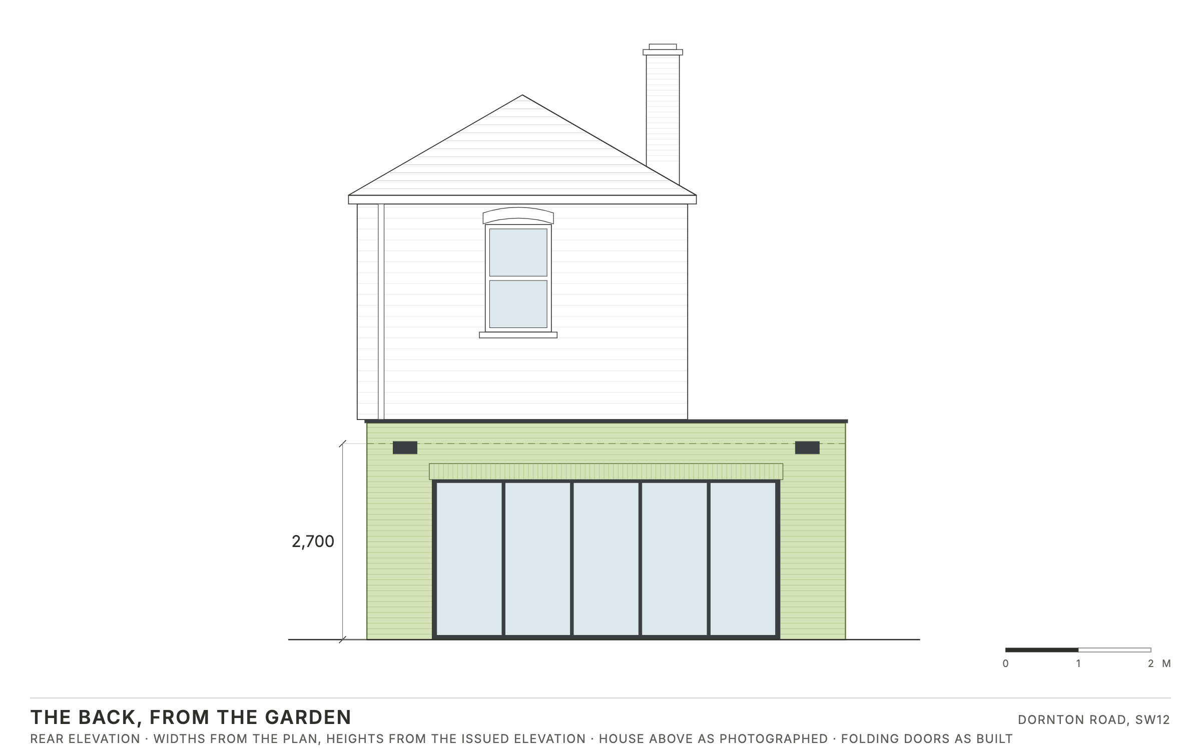
The back from the garden. The extension stands 2,700mm to the roof behind a parapet, with five folding door leaves under a soldier course. Widths come from the plan and heights from the issued elevation; the house above is drawn as it stands in the photographs.
Plate 04
Section
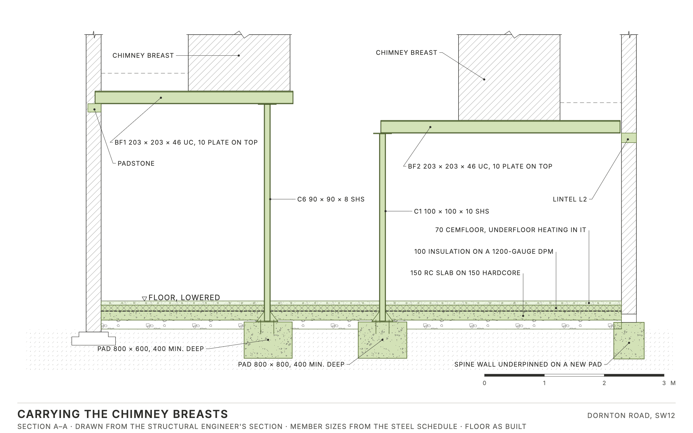
Section A–A, drawn to scale from the structural engineer’s section: how the chimney breasts are carried. BF1 and BF2 are 203 × 203 × 46 UC with a 10mm plate welded to the top flange; C6 and C1 are the columns, each on a base plate bolted to its own pad, and BF2’s far end sits on lintel L2 at the spine wall. The floor is drawn as built: one build-up wall to wall, lower than the old floor.
Plate 05
Sequence
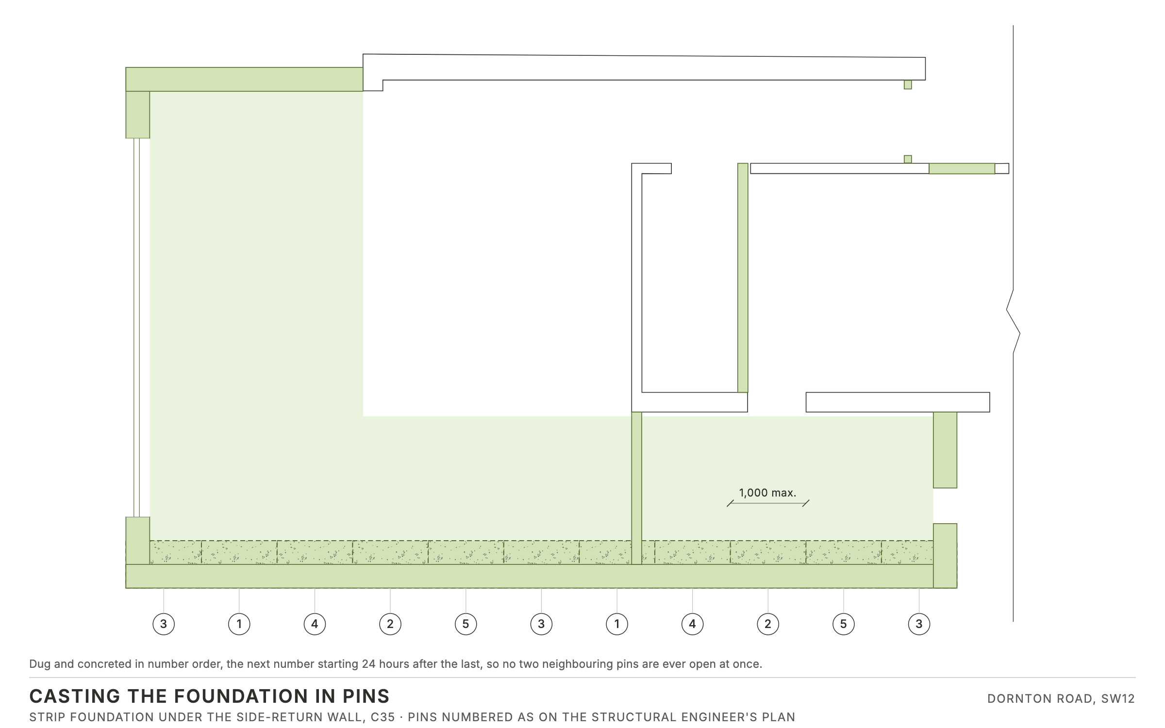
The strip under the side-return wall, numbered as on the engineer’s plan. Each number starts twenty-four hours after the last and every pin is concreted the day it is dug, so no two neighbouring pins are ever open.
Plate 06
Programme
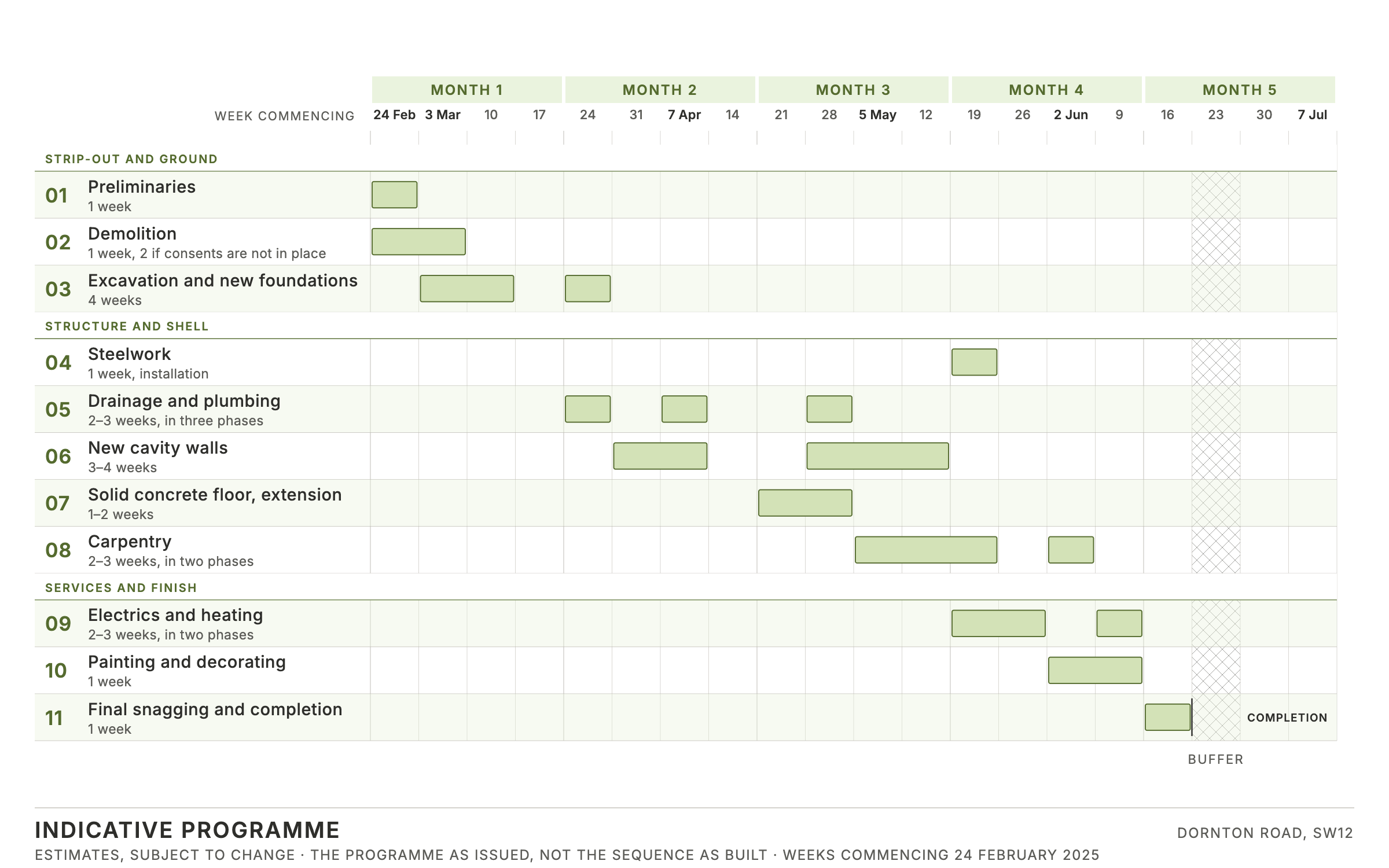
The programme as issued: eleven stages in three phases across a five-month window, with drainage in three visits, carpentry and electrics in two, and a week of buffer. Estimates, subject to change; this is the plan, not the sequence as built.
Specification
As specified
| Structure | Two chimney breasts carried on new steel beams BF1 and BF2, 203 × 203 × 46 UC with 10mm top plates; columns C6 90 × 90 × 8 SHS and C1 100 × 100 × 10 SHS, each on a 15mm base plate |
|---|---|
| Foundations | Strip 600mm wide and at least 500mm deep in C35 concrete, cast in pins of 1,000mm or less; pads 800 × 800 × 400 (800 × 600 × 400 under C6); formation at least 1.0m below ground |
| External wall | 100mm yellow London brick, 75mm rock wool cavity, 100mm Thermalite Shield block, stainless-steel ties, linked to the existing damp course |
| Floor | Whole flat, joists removed: concrete slab (150mm reinforced, on 150mm hardcore, in the extension), 1200-gauge DPM, 100mm insulation, 70mm CemFloor with the underfloor heating in it |
| Roof | Flat, fibreglass finish on 100mm Kingspan; three rooflights trimmed into the joists |
| Openings | Folding door set across the back wall in a 4,788mm opening, five leaves; doors and rooflights supplied and fitted by the client’s installer |
| Heating | Underfloor heating in six zones; combination boiler in a kitchen unit in the rear extension |
| Sound | Sound-insulated ceiling under the flat above, Rockwool Sound between the joists (variation) |
| Garden | Cleared and levelled, new soil compacted, new turf; new rear paving |
The build
Before to handover
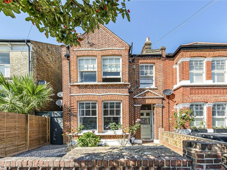
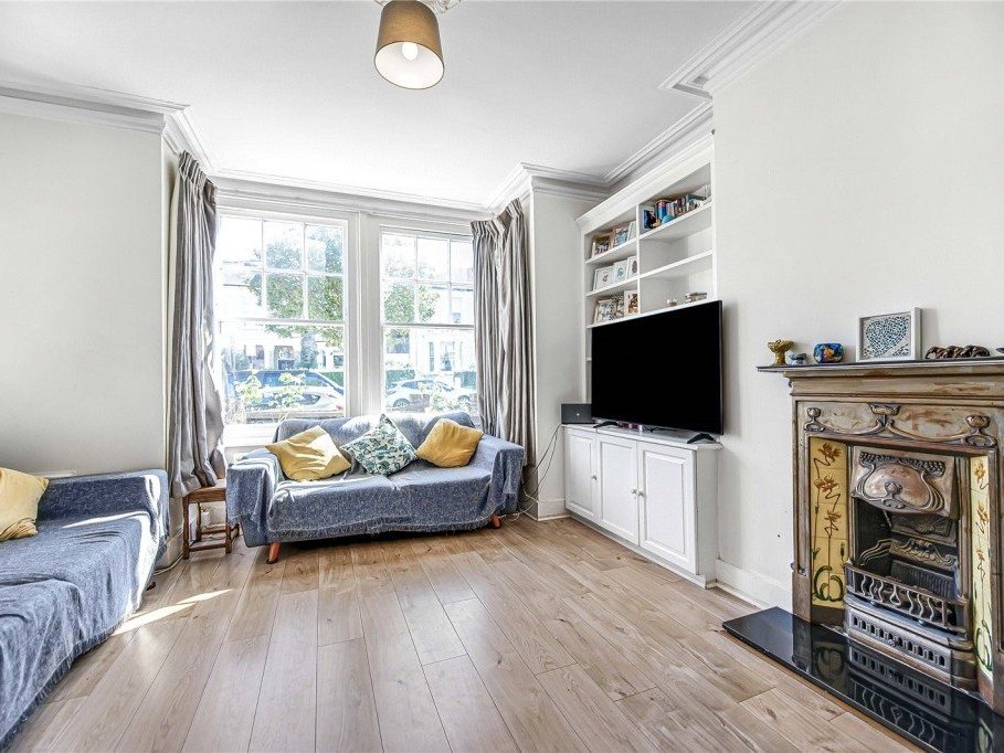
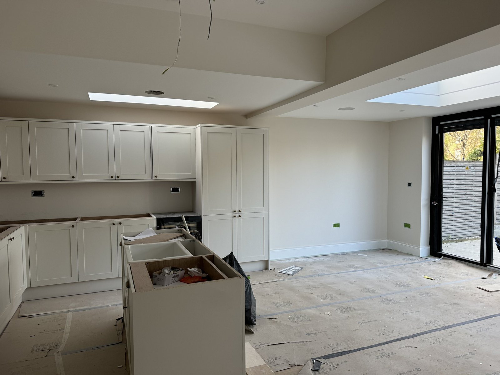
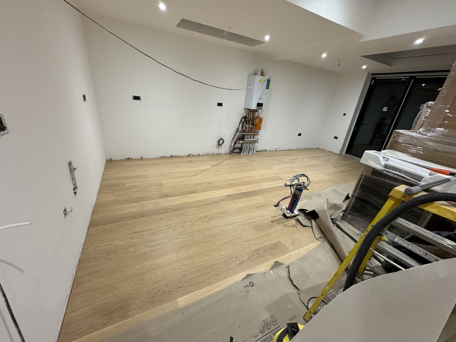
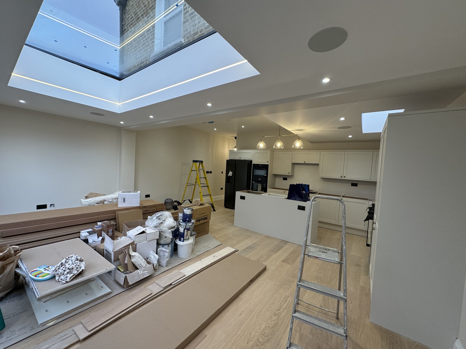
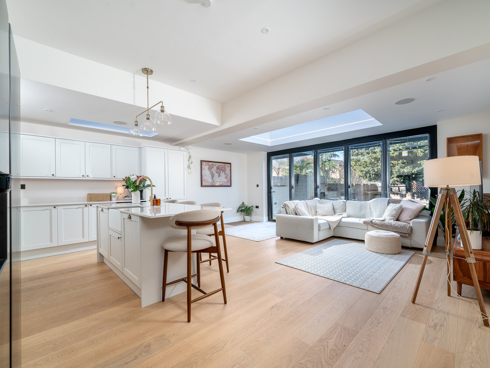
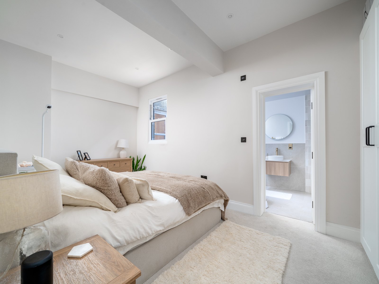
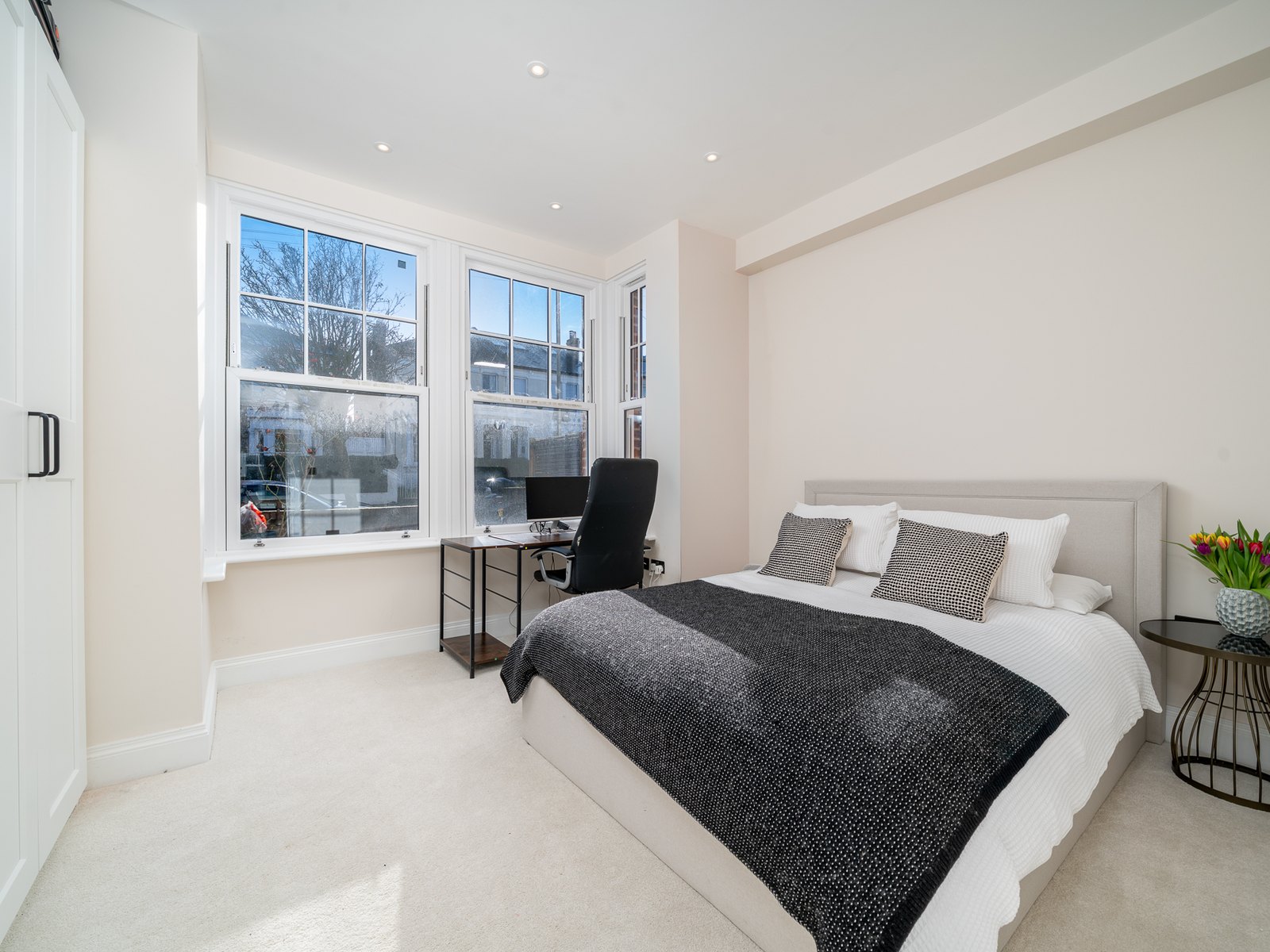
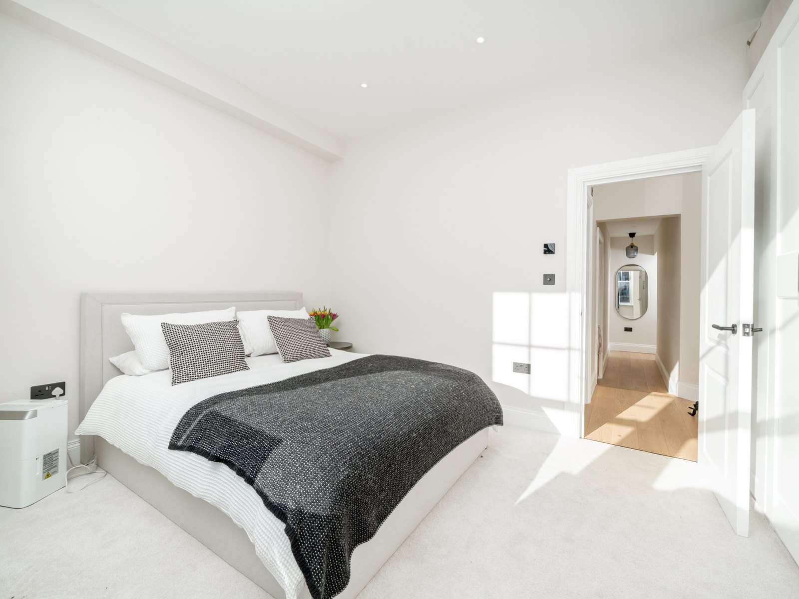
Main contractor O & K Property Works. Architect Oakman Architecture. Structural engineer create unlimited Structural Engineering. Drawings redrawn by OKPW, measured from the architect’s and the structural engineer’s issued drawings and the site photographs, and from OKPW’s own programme and specification: no plate reproduces another practice’s sheet. The plan, elevation and section are drawn to scale and carry scale bars.
Ask us the rest →